ERW tube defect diagnostic guide
The location where a defect is noticed is not necessarily the location where it began. A weld split can originate in strip preparation, edge forming, the fin section, heat input, forging pressure, material variation, or cooling. A sizing mark may be caused by tooling condition, but it may also begin with an oversized or unstable welded tube entering the sizing section.
Originally published in the ASTM A513 handbook (astma513.com), where specification-scoped A513 reference material remains.
Treat the symptom as evidence, not as the diagnosis. Contain affected material, preserve the process state, identify the first stage where the condition becomes detectable, and prove or eliminate causes from upstream to downstream.
This guide supports investigation. It is not a running-machine adjustment procedure and does not establish acceptance criteria.
Begin with containment
Before changing settings:
- Identify the potentially affected time, coil, heat, tooling state, order, and quantity.
- Segregate suspect material using the plant's nonconforming-product process.
- Preserve representative samples from the first observed failure and nearby acceptable production.
- Record the process state before adjustment.
- Determine which requirement or approved standard is not being met.
- Escalate conditions involving possible safety, weld integrity, material identity, or customer-critical characteristics.
Immediate containment and permanent corrective action are different decisions. A temporary process response may stop additional suspect production without proving root cause.
Safety boundary: Tube-mill investigation and maintenance must follow site lockout/tagout, guarding, stored-energy, electrical, pinch-point, hot-work, lifting, and qualified-person procedures. Never inspect, measure, clean, thread, or adjust moving equipment unless an approved procedure explicitly permits the task and provides the required safeguarding.
Preserve a useful evidence bundle
An investigation becomes much harder after tooling is removed, settings are changed, samples are mixed, or the process history is lost. Preserve:
- Defect photographs with scale and location
- Part, order, coil, heat/lot, time, and operator/shift identifiers permitted by policy
- Actual thickness, strip width, camber, burr, and edge condition
- Roll-set identity, drawing revision, regrind cycle, shim/spacer state, and last setup
- Machine-integrity and alignment status
- Pass-by-pass dimensions or witness evidence
- Welder power/mode, line speed, pressure/upset, cooling, and scarf conditions
- First-piece and recent in-process inspection results
- Location around the circumference and distance from the leading end
- Whether the condition is continuous, periodic, random, or tied to a coil transition
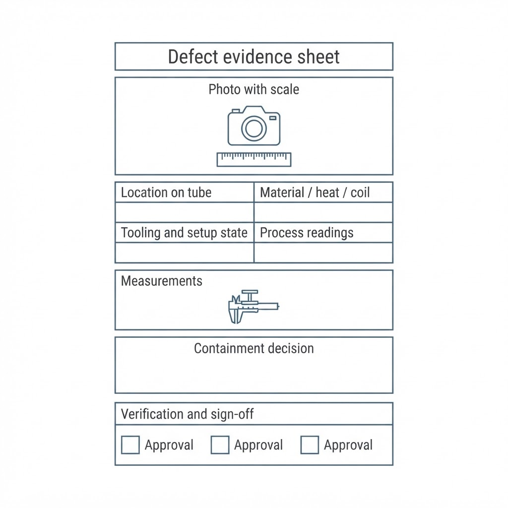
A defect evidence sheet: photo with scale, location, material identity, tooling state, process readings, measurements, containment, and verification.
When possible, include a known-good comparison from the same product family.
Use the first-detectable-stage method
Work through the line in process order:
- Incoming coil and slit edge
- Entry and centering
- Breakdown passes
- Side passes
- Fin passes
- Weld box and heat source
- Scarfing and cooling
- Sizing or reshaping
- Straightening and exit handling
- Cutoff, packaging, and transport
The first stage where the condition can be detected narrows the investigation. It does not automatically identify the root cause, but it prevents the team from adjusting equipment that has not yet contacted the affected feature.
Forming-related symptoms
| Observed symptom | Possible contributors | Evidence and first checks |
|---|---|---|
| Strip tracks side to side | Entry movement, camber, unequal drag, loose stands, nonparallel rolls, incorrect side-roll position, asymmetric wear | Confirm material condition and entry location; inspect stand integrity; compare inboard/outboard geometry and first-pass edge form |
| Edge wave or buckling | Light wall, insufficient edge support, slit camber or burr, wide stand spacing, unequal bearing drag, incompatible breakdown progression | Map where the wave first appears; compare strip edges; verify tooling identity, stability, alignment, and material actuals |
| Heavy-wall edge damage or flat spot | Excessive early work, inadequate support, shaft or stand deflection, incompatible incoming geometry | Compare both edges, pass progression, and contact evidence; inspect machine stiffness and roll condition under approved procedures |
| Material gathers between passes | Drive progression mismatch, excessive upstream pressure, downstream restriction, material riding a flange, incorrect strip width | Identify the first accumulation point; compare pitch/throat conditions, motor behavior, pass pressure evidence, and flange contact |
| Twist begins in forming section | Entry not square, unequal pass pressure, improper roll match, stand movement, spindle alignment, friction or orientation constraint | Verify entry and stand references; compare side-to-side contact and dimensions; distinguish persistent geometric twist from handling damage |
| Surface scuff starts at a breakdown or side pass | Relative slip, pickup, excessive pressure, wrong pass height, contaminated lubricant, incompatible tooling material | Locate the exact first marked pass; inspect contour and pickup; confirm lubricant condition and incoming surface |
Forming-related symptoms, possible contributors, and evidence and first checks
Do not respond to an edge wave by tightening later passes until strip condition, mechanical integrity, and the designed forming progression have been checked. The later adjustment may temporarily hide the symptom while adding thickness variation, marking, or instability.
Fin-section symptoms
| Observed symptom | Possible contributors | Evidence and first checks |
|---|---|---|
| Fin marks or fine edge shavings | Excessive incoming girth, worn/damaged fin blade, high reduction, nonparallel rolls, wrong pass height, speed mismatch | Measure after each fin; inspect blade and rim condition; compare intended and actual reduction progression |
| Edges are not parallel entering weld | Incomplete or unequal edge forming, damaged fin tooling, pass misalignment, incorrect strip width, unequal reduction | Photograph edge presentation; compare both sides; confirm first fin loading and the condition after every driven fin |
| Edge mismatch changes through a coil | Material-property or width variation, camber, unstable entry, tooling movement, heat-related movement | Correlate the symptom with coil position, material measurements, stand stability, and process temperature |
| Weld operation appears to carry excessive forming work | Last-fin contour does not match weld-roll need, insufficient fin reduction, edges improperly conditioned | Compare the last-fin exit with the weld-roll entry and the approved tooling/setup design |
Fin-section symptoms, possible contributors, and evidence and first checks
Weld-related symptoms
| Observed symptom | Possible contributors | Evidence and first checks |
|---|---|---|
| Centerline seam split | Edge mismatch, poor slit edge, uneven or insufficient heat, low forging pressure, excessive/unstable speed, material variation | Preserve the fracture; inspect edge match and heat pattern; compare speed, power, pressure, chemistry, hardness, and qualified weld-test results |
| Split adjacent to the seam | Excessive heat, susceptible chemistry/hardness, rapid cooling, residual stress | Confirm exact fracture location metallographically where warranted; review heat and cooling history; verify material identity |
| Pinholes or intermittent seam openings | Edge damage, contamination, unstable presentation, insufficient fin work, power/speed mismatch, localized material condition | Determine periodicity and circumferential location; inspect edge and weld evidence; correlate with process logs |
| Mismatched edges | Unequal forming, weld box off center, roll wear, incorrect setup, strip tracking, asymmetric material condition | Compare upstream edge presentation, multi-axis welded dimensions, weld-box references, and tooling wear |
| Weld chatter or poor external scarf | Insufficient or inconsistent upset, unstable tube support, bead temperature, scarf position or condition, speed variation | Preserve scarf chips and affected tube; inspect support and tool condition using approved procedures; compare weld and scarf timing |
| Weld is sound but tube is out of round | Weld-roll setup, incoming fin geometry, roll wear, circumference reading used without multi-axis confirmation | Measure top, side, and diagonal axes; compare with the last-fin exit and weld-box setup evidence |
Weld-related symptoms, possible contributors, and evidence and first checks
A fracture surface can contain evidence about heat, forging, contamination, and material response, but visual inspection alone may not prove the cause. Use qualified destructive testing, metallography, or laboratory support when the risk warrants it.
Surface-related symptoms
| Observed symptom | Possible contributors | Evidence and first checks |
|---|---|---|
| Continuous longitudinal mark | A fixed contact point, damaged contour, pickup, guide contact, scarf/support contact | Trace the mark upstream until it disappears; compare its clock position with contacting equipment |
| Periodic mark | Rotating tooling damage, runout, repeating weld/scarf condition, handling roller damage | Measure repeat length; relate it to roll circumference, rotation, cutoff, or handling interval |
| Random scratches | Contamination, loose scale/chips, handling, packaging, mixed material | Preserve debris; examine entry, coolant/filtration, exit tables, bundling, and transport |
| Pickup or galling | Material/tooling compatibility, relative slip, high pressure, inadequate or contaminated lubrication | Identify first contact location; inspect tool surface and lubricant; verify speed and height relationships |
| Sizing marks | Oversized/unstable incoming tube, excessive sizing work, worn or misaligned rolls, incorrect metal line, hot tube | Measure welded condition before sizing and after every driven sizing stand; inspect regrind/shim state |
Surface-related symptoms, possible contributors, and evidence and first checks
The clock position of a mark is useful only when the tube has not rotated between the source and the inspection point. Record seam orientation and known rotation through the line.
Dimensional and straightness symptoms
| Observed symptom | Possible contributors | Evidence and first checks |
|---|---|---|
| OD or perimeter varies | Material thickness/width change, unstable forming or weld, drive mismatch, worn tooling, thermal variation | Trend pass-by-pass dimensions, material actuals, speed/load, tooling state, and cooling |
| Ovality or diagonal distortion | Incorrect welded geometry, unequal roll loading, alignment, roll wear, sizing imbalance | Measure multiple axes at weld and after each sizing pass; do not rely on one circumference reading |
| Wall appears uneven | Incoming thickness variation, edge damage, forming strain, measurement location/method, sample preparation | Confirm incoming thickness map and measurement method; distinguish true wall change from burr or preparation error |
| Bow after cooling | Uneven or insufficient cooling, support, sizing/straightening state, residual stress | Compare temperature and support conditions; locate where bow first appears |
| Twist in shaped tube | Forming progression, unequal work, tooling alignment, weld location, reshape balance, exit handling | Measure twist by a defined method at multiple stages; compare seam orientation and first-detectable stage |
| Length variation | Cutoff synchronization, speed measurement, thermal state, slippage, encoder or measurement issue | Compare commanded length, line speed, actual length, cutoff condition, and measurement-system status |
Dimensional and straightness symptoms, possible contributors, and evidence and first checks
See the mechanical tubing inspection and first-piece guide on this site for measurement planning and release evidence.
Documentation and identity failures
Not every nonconformance is a geometric defect. Treat these as product-control failures:
- Material identity cannot be traced to the order
- The wrong tooling or setup revision was used
- Required testing was missed
- Certification does not match the product
- A deviation was used without approval
- Gauges were out of calibration or unsuitable
- Suspect product was mixed with accepted product
- The process record cannot reconstruct what was produced
Contain documentation failures with the same discipline used for visible defects. A tube that measures correctly but lacks required identity or evidence may still be nonconforming.
A disciplined investigation workflow
- Define the failure. Quote the actual requirement and measurement method.
- Contain. Establish the affected boundary and preserve samples.
- Freeze evidence. Record the last known process state before adjustment.
- Locate first detection. Move upstream until the symptom disappears.
- Separate integrity from setup. Prove components are mechanically sound before precision alignment or setting changes.
- Test one causal hypothesis at a time. Record the expected and actual result.
- Confirm the correction. Use an adequate run and measurement sample, not one apparently good piece.
- Prevent recurrence. Update the controlled setup, PM, tooling, inspection, training, or purchasing record.
Avoid changing several settings simultaneously. A multi-variable adjustment may restore production without showing which change mattered, making recurrence likely.
How to read the symptom tables
The tables list plausible contributors, not diagnoses. The same visible symptom can have several causes. Final investigation and corrective action require the actual mill, material, tooling, qualified personnel, controlled safety procedures, and order requirements.
Use the interactive defect atlas below to filter these symptoms by stage and cause category and assemble a safe first-check list for a specific investigation.
Check whether a matching run is already on order at Tightsteel, our related digital warehouse for steel tube — or send the requirement and get a mill run scoped. Runs are planned mill production, not shelf stock; the producing mill and country of origin are disclosed to you before you’re bound to anything.
See what's on order → tightsteel.com/warehouse
Tightsteel is a related commercial venture. See /disclosures.